-
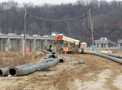
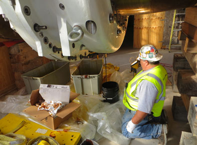
December -
HDPE pipe being welded and used to control fill upstream and downstream cells (photo courtesy of MWH)
-
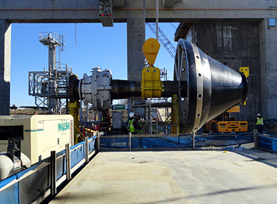
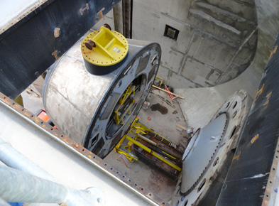
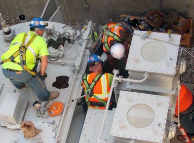
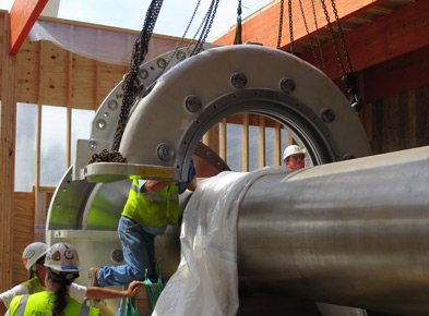
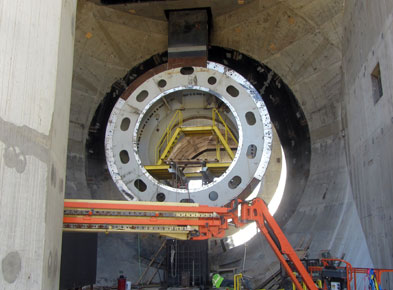
December -
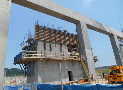
Assembly of the Unit 2 shaft and inner gate barrel on the powerhouse roof
-
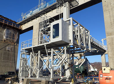
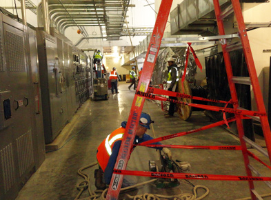
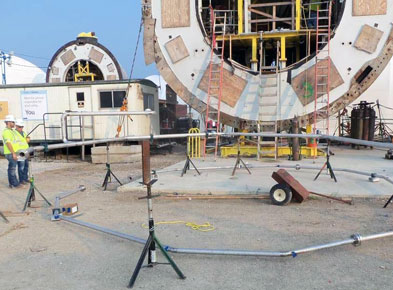
December -
Partially assembled trash rake equipment
-
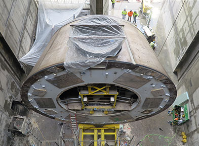
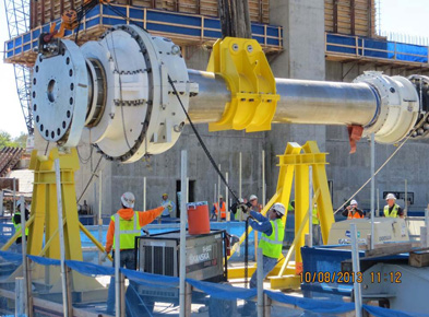
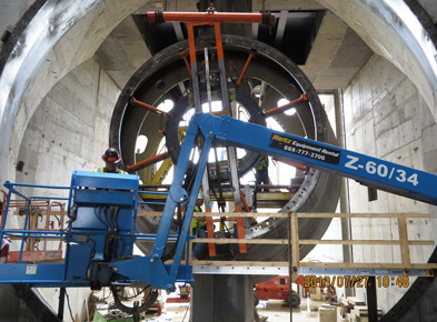
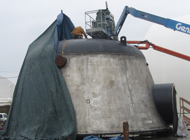
December -
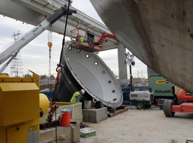
View of the bulb nose sitting on the installation rails
-
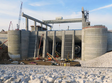
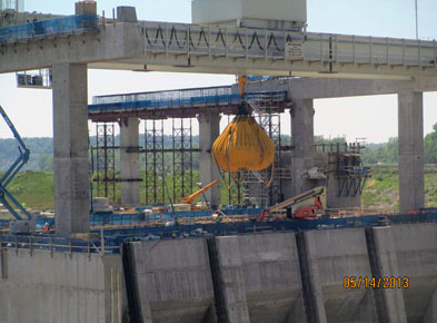
November -
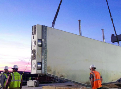
Setting the first section of the Unit 2 emergency gate (photo courtesy of MWH)
-
November -
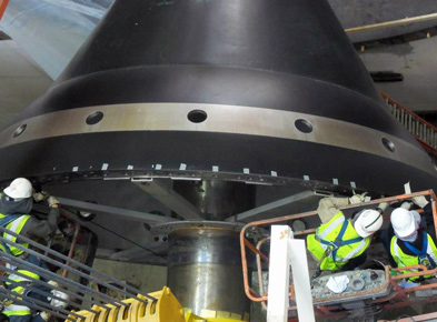
Installing the first O-ring for the Unit 1 inner gate barrel
-
November -
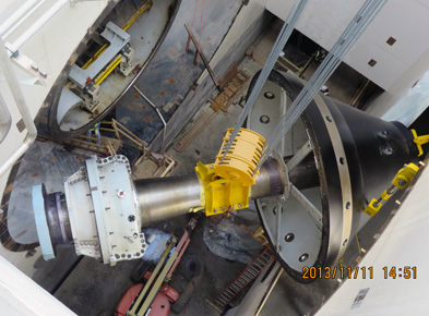
Lowering and rotating shaft and inner gate barrel into position in powerhouse
-
November -
Cleaning flange for Unit 2 inner gate barrel
-
October -
First cable pulling
-
October -
Unit 2 bulb nose in the hole and the combined bearing support installed
-
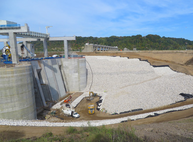
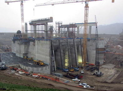
October -
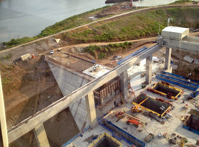
Overview of the intake area with Type A rip rap
-
October -
Setting the Unit 1 shaft and bearing on support stands on the powerhouse roof (photo courtesy of MWH)
-
September -
Flushing the oil from the combined bearing on the Unit 2 shaft (photo courtesy of MWH)
-
September -
View of the trash rack installation and the intake area with Type A rip rap
-
September -
Installing HV bushings for Unit 3 transformers (photo courtesy of MWH)
-
September -
Installing HV bushings for Unit 3 transformers (photo courtesy of MWH)
-
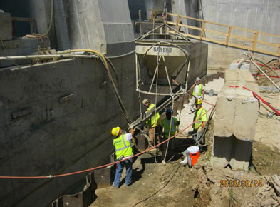
August -
Placing mortar for level surface needed for installation of the copper seal
-
August -
Placing rip rap bedding downstream of the powerhouse and riverside closure structure
-
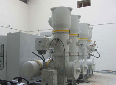
August -
Assembling the gas insulated switchgear equipment (photo courtesy of MWH)
-
August -
Installing reinforcing steel for the upstream landside closure structure facing concrete (photo courtesy of MWH)
-
July -
Re-machining of downstream inner cone
-
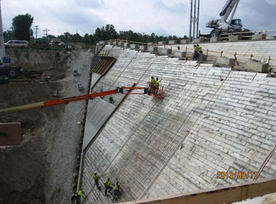
July -
Preparing for the 12" facing concrete and steel sheet pile concrete cap
-
July -
Setting Unit 1 upper half thrust bearing body onto shaft
-
July -
Preparing Unit 1 draft tube surface for gunite repair
-
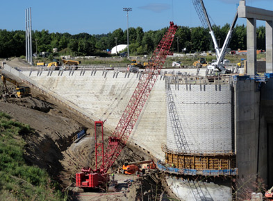
June -
Tower crane view of the riverside closure structure
-
June -
Carpenters forming the riverside access building (photo courtesy of MWH)
-
June -
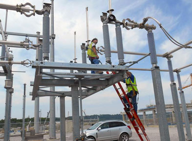
Installing brackets on motor-operated disconnects in the switchyard
-
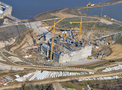
June -
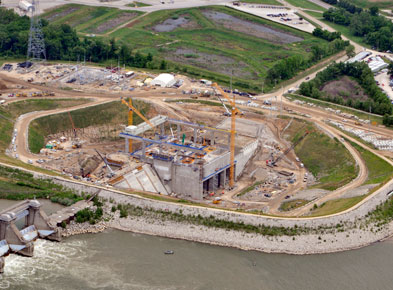
Aerial view
-
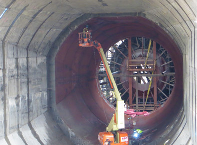
May -
Installing platforms in the bulb turbine housing
-
May -
Water weights used to perform powerhouse crane load test (photo courtesy of MWH)
-
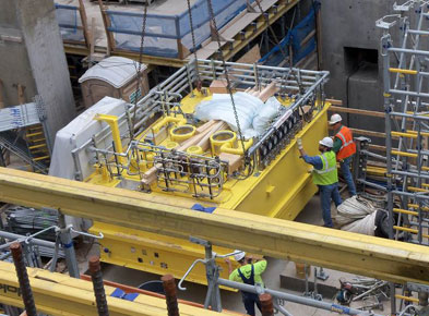
May -
Crew setting Unit 2 governor HPU (photo courtesy of MWH)
-
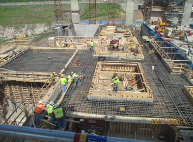
May -
Crew installing formwork for roof slab
-
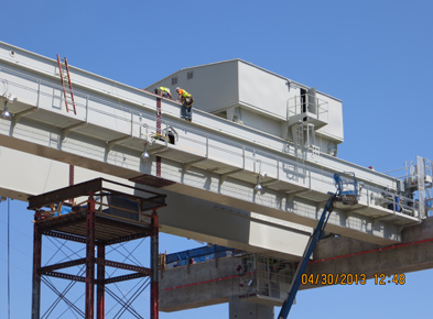
April -
Crane erection with installation of the crane trolley
-
April -
View of the intake and powerhouse crane girder G2
-
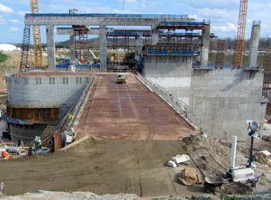
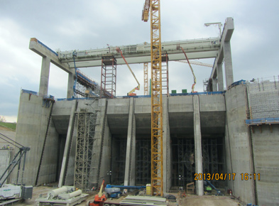
April -
Riverside closure structure hardfill completed
-
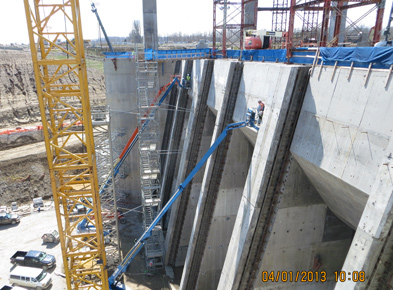
April -
Working on the intake gate guide rail installation
-
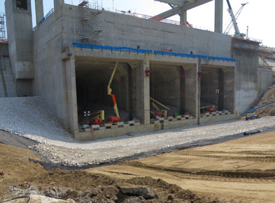
March -
Landside closure structure and intake area
-
March -
Removing bracing supports for draft tube liner
-
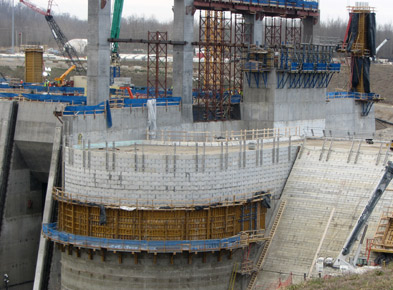
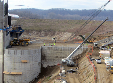
March -
Riverside closure structure
-
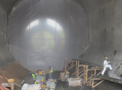
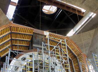
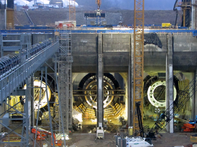
March -
View of second stage concrete bulb turbine housing and stay cone
-
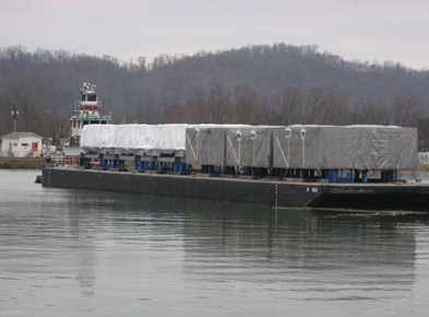
February -
Barge loaded with 3 distributors and 3 stators leaving Voith facility headed to Cannelton
-
February -
Moving the Unit 1 generator access hatch into position (photo courtesy of MWH)
-
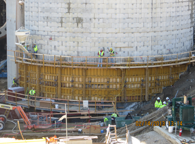
February -
Placing the 12î concrete liner on the upstream end of the riverside closure structure
-
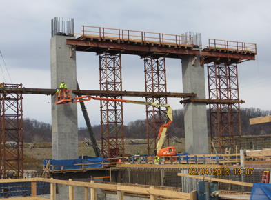
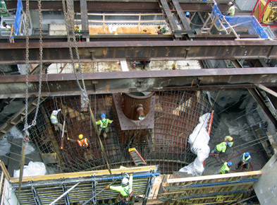
February -
Installation of bracing and shoring support underway for the crane beam
-
January -
Preparing to weld the bulb nose cap to the bulb nose cone
-
January -
Night view of the intake area
-
January -
View of the riverside closure structure
-
January -
Aerial view